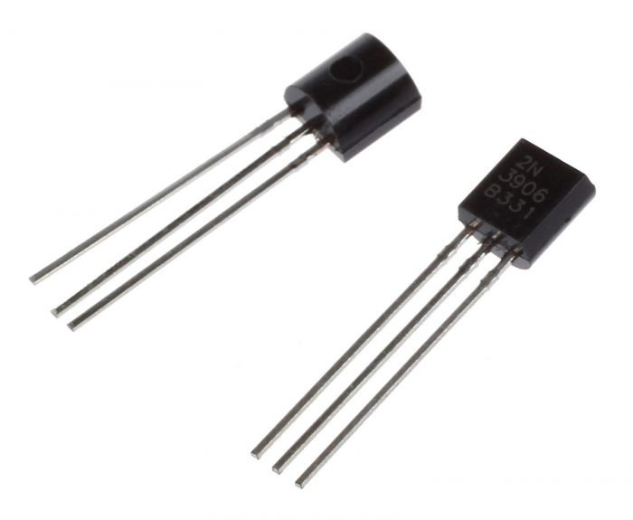

Some equivalent transistors have the opposite pinout (E,B,C) and some are B,C,E. The 2N3904 comes in a TO-92 case with leads in the order C,B,E.

So just look for a substitute that has H FE of at least 100 at an I C of around 10mA, and you should be OK.įinally, before settling on a particular part you might want to check its Packaging - case style, lead designations etc. In your circuit higher gain is better, but 100 is plenty enough. Any substitute that is within or close to that range should be fine (assuming the circuit was designed to accommodate such a wide variation). The manufacturer may sort them and label similar units with the same part number, but they don't throw away any that aren't identical because that would make the 'perfect' remainders too expensive.Īt 10mA Collector current the 2N3904's current gain could be anywhere between 100 and 300. Functional operation above the RecommendedOperating Conditions is not implied. The diffusion process that creates its elements is not precise, so every transistor that is produced has different characteristics. Transistors PNP Silicon Features PbFree Packages are Available MAXIMUM RATINGS THERMAL CHARACTERISTICS (Note 1) Stresses exceeding Maximum Ratings may damage the device. Why so many numbers? The reason relates to how transistors are made. Instead you are given a range with minimum, maximum, and perhaps 'typical' values for different currents and voltages. But confusingly, the datasheet doesn't provide a single number. That leaves DC current gain as the essential parameter that must be duplicated. So you don't have to worry about high frequencies, AC signals, or switching speed, and you have plenty of voltage available so saturation voltage is not critical. Your circuit compares a slowly changing DC voltage to an adjustable reference voltage, and switches on one of two LEDs. Depending on the application, some may be more important than others. Your circuit is only powered with 9V, and the current passing through each transistor is limited to less than 20mA, so any replacement that can handle eg. The 2N3904 is rated for a maximum of 40V between Collector and Emitter, and 200mA Collector current. The perfect replacement would have the same or higher ratings, but they could be lower provided that your circuit doesn't come close to them. These must never be exceeded, or the device will fail. Top of the list is Absolute Maximum Ratings. The chances of of finding an identical substitute are slim, so you will have to decide which numbers are important, and how closely they must match. But beyond that the datasheet may provide a lot of parameters. Obviously the replacement must be of the same type (bipolar NPN) and preferably designed for the same applications (general purpose amplifier). These transistors are available in package styles TO-92, SOT23, SOT223 with different prefixes.First, find the datasheet of the device you want to replace.

The 2N3904 (NPN) and 2N3906 (PNP) are complementary transistor pairs. Its transition frequency F t is 250 MHz, with a beta of at least 100. The 2N3906 is specified by a collector current of 200 mA, collector-base and collector-emitter voltages of 40 V, for power dissipation of 300 mW. When looking at the flat side with the leads pointed downward, the three leads emerging from the case are, from left to right, the emitter, base, and collector leads. The 2N3906 is manufactured in a plastic TO-92 case. Both types were registered by Motorola Semiconductor in the mid-1960s.ĭevice packaging and specifications It is complementary to the 2N3904 NPN transistor. It is designed for low electric current and power and medium voltage, and can operate at moderately high speeds. The 2N3906 is a commonly used PNP bipolar junction transistor intended for general purpose low-power amplifying or switching applications. The upper-left and lower-right quadrants are bonding pad areas where wires for two of the terminals are attached, and the other two quadrants have the actual transistor structures, in a bulk region that is contacted at the back side of the chip to the third terminal. Photomicrograph of the transistor chip inside a 2N3906 transistor package, showing the conductive metal layers used to connect the semiconductor junctions to the package leads.


 0 kommentar(er)
